Total Frequency Control News ....
G-SENSITIVITY IN QUARTZ RESONATORS - July 2013
Quartz crystals are a piezoelectric device, the name of which is derived from Greek and means a pressure electric device. Applying an electric field to a piezoelectric device causes it to deform and by applying a reversed polarity field, the deformation is reversed. This forms the basis of quartz crystals being used in oscillators as it is possible to set the feedback conditions in an electrical circuit such that the resonance of a specific piece of quartz is maintained. The very high Q available from quartz means that it is possible to manufacture very accurate frequency sources and by means of temperature compensation it is possible to achieve stabilities that approach atomic standards.
Given that the quartz is pressure sensitive, the stabilities achieved in precision oscillators can be modified by external influences, one of which is gravity. Manufacturers will often talk of a specification parameter called the g-sensitivity of the crystal. Typical values of g-sensitivity run from 1x10⁻⁷ for low cost AT cut resonators, to better than 1x10⁻¹⁰ for precision SC cut resonators. One method of characterising the g-sensitivity figure is to measure the resonator in an oscillator and then invert the unit. Turning the unit through 180 degrees imparts a gravitational force of 2g on the unit, often specified as a 2g tip-over test. This, however, is only a static measurement and does not give any real information on the performance of such a unit in a high g environment.
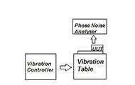
As the phase noise of an oscillator degrades under shock and vibration it is possible to measure the g-sensitivity of the oscillator in an operational environment. This will require the use of shock and vibration equipment coupled with good phase noise measuring equipment. Random vibration is applied to the unit, typically from 10 Hz to 2KHz, and the deviation in phase noise is measured.
The effects of random vibration on the unit under test causes a rise in the noise floor of the oscillator and since the power spectral density of the vibration is known, it is possible to calculate the g-sensitivity of the unit.
Care has to be taken to allow for specific resonances in the mounting jig and test set up as these resonances build and amplify the effects of the g-sensitivity. The data below shows a typical set of data for a unit in three axes. The plots show jig resonances causing some distortion at the higher frequencies.
The above data is the usual starting point for designing product to meet a specific requirement or application and forms the base line against which improvements can be measured. Improvements can be made by paying particular attention to the crystal design, mounting points and even the bonding epoxies employed. Damping can be incorporated into the oscillator design if space permits. By studying the g-sensitivity in each axis it may be possible to optimise the customer’s performance and specify a specific mounting orientation.
Please send any enquiries to sales@tfc.co.uk
Other News Items
NEWS

TFC’s high quality, miniature ceramic smd, crystal clock oscillator manufactured over the wide ... more
TFC’s comprehensive range of SMD power inductors have an inductance value from 1uH to 1500uH ... more